Difference between revisions of "3DOs for Evil Geniuses-in-Training"
Bernd Nowak (Talk | contribs) m (Text replace - 'gplmz.bcsims.com' to 'srmz.net') |
|||
| Line 10: | Line 10: | ||
===Tool Up=== | ===Tool Up=== | ||
| − | + | *Get a Hex Editor (see http://www.winfiles.com/ and do a search for UltraEdit or HexEdit, or something similar) | |
| − | + | *Get Paul Hoad's Track Editor. Download here: [[http://srmz.net/index.php?showtopic=3332 http://srmz.net/index.php?showtopic=3332]] and be prepared for crashes if you press the wrong thing. | |
===Background=== | ===Background=== | ||
| − | + | *Read all the pages at [[http://www.vanwall.eclipse.co.uk/gplediting/ http://www.vanwall.eclipse.co.uk/gplediting/]], especially the 3DO pages. | |
| − | + | *Read them again. | |
| − | + | *Read them again, make notes, and read again. | |
===3DO Sections=== | ===3DO Sections=== | ||
| Line 26: | Line 26: | ||
Each 3DO file consists of a number of sections, containing specific information: | Each 3DO file consists of a number of sections, containing specific information: | ||
| − | 3DO4: Always present at the beginning of the file. Just a short header block. | + | '''3DO4''': Always present at the beginning of the file. Just a short header block. |
| − | NORM: Rarely present. Contains normals for fancy lighting. Don't worry about these. | + | '''NORM''': Rarely present. Contains normals for fancy lighting. Don't worry about these. |
| − | SXYZ: Always present. Contains vertices. The X & Y axes are on the ground, with Z pointing up. S is unused (0.0). | + | '''SXYZ''': Always present. Contains vertices. The X & Y axes are on the ground, with Z pointing up. S is unused (0.0). |
| Line 36: | Line 36: | ||
| − | PLAN: Planes. A Plane is an infinitely thin 'sheet' dividing 3D space into two parts - above and below the plane. The definition of the planes used in GPL is Ax+By+Cz+D=0, where sqrt(A*A + B*B + C*C)=1.0, e.g. a unit-length normal. See the incredible graphic that is figure 2... | + | '''PLAN''': Planes. A Plane is an infinitely thin 'sheet' dividing 3D space into two parts - above and below the plane. The definition of the planes used in GPL is Ax+By+Cz+D=0, where sqrt(A*A + B*B + C*C)=1.0, e.g. a unit-length normal. See the incredible graphic that is figure 2... |
| Line 48: | Line 48: | ||
| − | STRN: Usually (95%) present. Contains null terminated strings (character 0x00 separates each string). These are filenames without extensions (e.g. fence instead of fence.mip). collision is a name which isn't a file, see later for details. | + | '''STRN''': Usually (95%) present. Contains null terminated strings (character 0x00 separates each string). These are filenames without extensions (e.g. fence instead of fence.mip). collision is a name which isn't a file, see later for details. |
| − | PRIM: The big one. Lots of nodes, which create a BSP tree structure for visibility calculations, polygons, collision volumes, and lilac underbukser. | + | '''PRIM''': The big one. Lots of nodes, which create a BSP tree structure for visibility calculations, polygons, collision volumes, and lilac underbukser. |
| − | HAND: The PRIM section by default only has one tree. By using this section (optional), you can create additional trees in the PRIM section and reference them here. Used for adding a collision volume, or a sound tree, or in the case of cars, a shed load of things (eeek!). | + | '''HAND''': The PRIM section by default only has one tree. By using this section (optional), you can create additional trees in the PRIM section and reference them here. Used for adding a collision volume, or a sound tree, or in the case of cars, a shed load of things (eeek!). |
| Line 62: | Line 62: | ||
Here goes. The simplest object you can create is a board, visible from one side only (e.g. a brake board). What do we need? | Here goes. The simplest object you can create is a board, visible from one side only (e.g. a brake board). What do we need? | ||
| − | + | *4 vertices, one per corner | |
| − | + | *1 plane, pointing out of the board | |
| − | + | *1 polygon | |
| − | + | *1 string, for the mip file that will be used to texture the polygon | |
| Line 97: | Line 97: | ||
| − | + | *'''Green''' is the 3DO4 header. 12 bytes long, and identical for all 3DO's, except the last 4 bytes, which = the number of bytes in the rest of the file. | |
| − | + | *'''Purple''' is the Vertices section (SZYX). It is 12 bytes long + (16*no. of vertices). The last 4 bytes of the 12 bytes = number of bytes in the vertices section (=no. vertices *16). Each vertex is in the order S X Y Z, and are 32bit floating point numbers - e.g. 00 00 80 3f = 1.0. | |
| − | + | *'''Blue''' is the Planes section (NALP). Same again - 12 bytes + (16*no. of planes). 4*32bit floating point numbers, in the order A B C D. | |
| − | + | *'''Orange''' is the String table. 12 bytes + a number of bytes which is a multiple of 4, padded with 0x20 bytes if too short. Inspect the bytes and it will make sense. | |
| − | + | *'''Yellow''' is the Primitives section (MIRP). 12 bytes, then 4 bytes, which is an offset to the first node in the three. E.g. here our first node is at offset 0x64, which when worked out is the 06 00 00 00 number 12bytes from the end, which is the type 6 node choosing a plane. This node then references the type 5 node before it in the file (05 00 00 00, 10 00 00 00, 05 00 00 00, 00 00 00 00, 02 00 00 00), which in turn references the type 81f node before that (1f 08 00 00, etc.). | |
A good understanding of the layout of the 3DO files is essential, because when you start adding a collision volume, or you try and delete things, you'll be hex editing. | A good understanding of the layout of the 3DO files is essential, because when you start adding a collision volume, or you try and delete things, you'll be hex editing. | ||
Latest revision as of 21:43, 5 May 2009
Authored by the GPLEA
(written with the Eurovision Song Contest on in the background. Please excuse all madness contained below)
Contents
[hide]Introduction
So, you want to make a 3DO object then, eh? Okay... These pages should help in your quest for enlightenment, which will probably take some time, so BE PATIENT! It’s important to realize that GPL does not use a depth buffer for visibility work. It uses a BSP-like tree structure instead.
Tool Up
- Get a Hex Editor (see http://www.winfiles.com/ and do a search for UltraEdit or HexEdit, or something similar)
- Get Paul Hoad's Track Editor. Download here: [http://srmz.net/index.php?showtopic=3332] and be prepared for crashes if you press the wrong thing.
Background
- Read all the pages at [http://www.vanwall.eclipse.co.uk/gplediting/], especially the 3DO pages.
- Read them again.
- Read them again, make notes, and read again.
3DO Sections
Each 3DO file consists of a number of sections, containing specific information:
3DO4: Always present at the beginning of the file. Just a short header block.
NORM: Rarely present. Contains normals for fancy lighting. Don't worry about these.
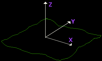
SXYZ: Always present. Contains vertices. The X & Y axes are on the ground, with Z pointing up. S is unused (0.0).
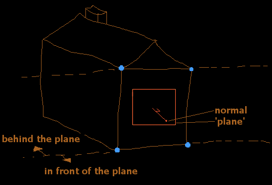
PLAN: Planes. A Plane is an infinitely thin 'sheet' dividing 3D space into two parts - above and below the plane. The definition of the planes used in GPL is Ax+By+Cz+D=0, where sqrt(A*A + B*B + C*C)=1.0, e.g. a unit-length normal. See the incredible graphic that is figure 2...
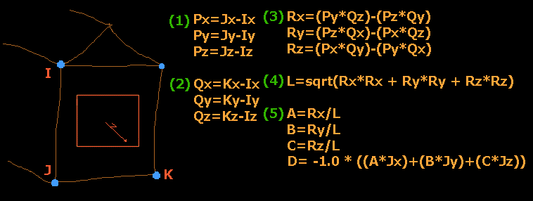
So once you know what direction your normal points in, you can calculate D by substituting in one of the vertices that lie on the plane. Alternatively, with 3 vertices that lie on the plane (no co-linear), this equation will give you a plane to match (fig.3). Remember that the vertices of a polygon are defined in anti-clockwise order, when looking at the polygon.
STRN: Usually (95%) present. Contains null terminated strings (character 0x00 separates each string). These are filenames without extensions (e.g. fence instead of fence.mip). collision is a name which isn't a file, see later for details.
PRIM: The big one. Lots of nodes, which create a BSP tree structure for visibility calculations, polygons, collision volumes, and lilac underbukser.
HAND: The PRIM section by default only has one tree. By using this section (optional), you can create additional trees in the PRIM section and reference them here. Used for adding a collision volume, or a sound tree, or in the case of cars, a shed load of things (eeek!).
(Eurovision has finished. Normal madness resumes in 3... 2... 1...)
Example Object
Here goes. The simplest object you can create is a board, visible from one side only (e.g. a brake board). What do we need?
- 4 vertices, one per corner
- 1 plane, pointing out of the board
- 1 polygon
- 1 string, for the mip file that will be used to texture the polygon
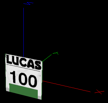
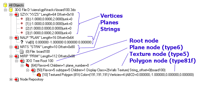
Here's what it will look like:
Those vertices are 0: (-1,0,2), 1: (-1,0,0), 2: (1,0,0), 3: (1,0,2).
This object, shown as a tree is:
Now, see how the tree is arranged - the type 6 node is first in the tree, which makes everything descended below it only visible when the viewer is in front of the plane referenced by that node (plane 0, which is (0,-1,0, 0) - pointing out of the front of the board, centered at (0,0,0)).
Next is the type 5 node, which chooses the texture we want for the board - in this case the only string, which is value 0 = board100.
Finally, the tree contains a type 81f node, which is a textured polygon. This polygon uses all 4 vertices, 0,1,2,3, and texture coordinates 0=(0,0), 1=(0,1), 2=(1,1), 3=(1,0).
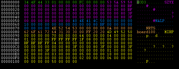
Now, let's have a look at board100.3do in a hex editor... (muahahahahaaaa)
- Green is the 3DO4 header. 12 bytes long, and identical for all 3DO's, except the last 4 bytes, which = the number of bytes in the rest of the file.
- Purple is the Vertices section (SZYX). It is 12 bytes long + (16*no. of vertices). The last 4 bytes of the 12 bytes = number of bytes in the vertices section (=no. vertices *16). Each vertex is in the order S X Y Z, and are 32bit floating point numbers - e.g. 00 00 80 3f = 1.0.
- Blue is the Planes section (NALP). Same again - 12 bytes + (16*no. of planes). 4*32bit floating point numbers, in the order A B C D.
- Orange is the String table. 12 bytes + a number of bytes which is a multiple of 4, padded with 0x20 bytes if too short. Inspect the bytes and it will make sense.
- Yellow is the Primitives section (MIRP). 12 bytes, then 4 bytes, which is an offset to the first node in the three. E.g. here our first node is at offset 0x64, which when worked out is the 06 00 00 00 number 12bytes from the end, which is the type 6 node choosing a plane. This node then references the type 5 node before it in the file (05 00 00 00, 10 00 00 00, 05 00 00 00, 00 00 00 00, 02 00 00 00), which in turn references the type 81f node before that (1f 08 00 00, etc.).
A good understanding of the layout of the 3DO files is essential, because when you start adding a collision volume, or you try and delete things, you'll be hex editing.
Get two other simple objects here:
Object 2, a 5-sided Box
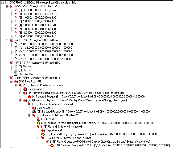
Take a look at t9box.3do in GPLTrackEditor. Notice how every wall is behind all the others. Take a viewer in front of the 'door' wall. If they were looking at the object, we know for certain that everything behind the 'door' wall needs to be drawn before the 'door' wall itself.
The same applies to the other walls. Even the roof has all the walls behind it.
As a tree, this object may look weird. It is weird, but it is perfectly legal 3DO, and will display correctly in GPL:
Before looking at the tree, try and figure the relation between the vertices, which define the polygons, and the planes, which define the visibility. As a guide - the first plane [0] points out of the door, [1] points out of the right hand wall, [2] points out of the rear wall, [3] points out of the left wall, and [4] points out of the roof.
Draw a diagram of these, along with the xyz axes to 'realize' the things going on...
The Tree
Type 9 nodes are like type 6 nodes, with the middle child pointing to the bits of tree to be drawn 'on' the plane. Type 9 nodes have two other children. The first contains the tree nodes containing things that are in front of the plane, the last containing those things that are behind the plane.
See the first 9 node, which has the door polygon as its middle child. This node references the [0] plane; the node 5 references the door string (at location 5 in the string table), and the polygon (81f) references vertices 0,1,2,3.
This node has a type 5 node as its third child. This is because we want all nodes descending from here to be textured with the same texture - 'wall'. This saves adding the same node 5 over and over again, and we can still change textures as and when needed later on.
The second type 9 node references plane [1], and contains the polygon for the right-hand wall.
Then the third type 9 node, [2], with the back wall.
Then the fourth type 9 node, [3], with the left-hand wall.
Lastly, there is a type 6 node, [4], with the roof polygon. We don't need any more nodes in the tree after this one, so a type 6 node suffices. Note how there is a type 5 node here to change to the 'roof' texture.
All for now...
Last updated: 24-May-2003
(c) Guru http://gplea.rscsites.org/
Transfered to the wiki: 14.04.2009
