GPL Track Creating - Altitude Tutorial
Authored by Phil Flack
This page will attempt to explain how to create altitudes for GPL tracks. If you don't understand the maths, it may be quite difficult to understand at first, but I'll do my best to explain it in an easy way.
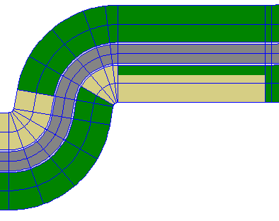
Let's look at a bit of a TRK first -
Here you can see that every section of the track has the same traces (blue lines- not the blue lines between each section though), always in the same lateral (left-right) position. For the purposes of altitudes, there is no difference between corners and straights, except of course that on corners, space is either compressed (near centre of turn) or stretched (away from centre). The only affect that this may have, is that altitude changes may seem more or less extreme depending on turn. There is one altitude defined per trace, per section. So if you have 90 sections in your track, and 10 traces, you will have 900 altitudes defined.
Each altitude is a cubic curve, represented by 4 values - Start Height, cubic coefficient, square coefficient and linear coefficient. The function that defines the height at any position along the curve is:
Where z is the vertical position (height), d1 is the cubic coefficient, d2 is the square coefficient and d3 is the linear coefficient. (Note- in GPLTrk, d1=3rd order, d2=2nd order, d3=1st order). t is a value from 0 (start of altitude/section) to 1 (end of altitude/section).
Math section - ignore if you want to!
Further more, we can calculate the gradient at any point on the curve with this equation:
Now, with some nifty substitutions and known values, we can calculate the 3 delta values. With Start Height, End Height, Start Angle, End Angle, and Length of Altitude (= Section Length for straights, but identical maths can be used for corners, by pretending that they are straights). 3 simple calculations (in the order shown), will give the delta values.
Gradient is calculated from the angles and section lengths:
End of maths bit
So how does all this let us make Eau Rouge MkII?
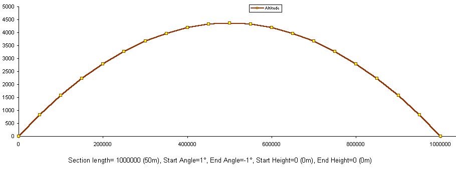
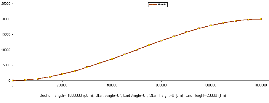
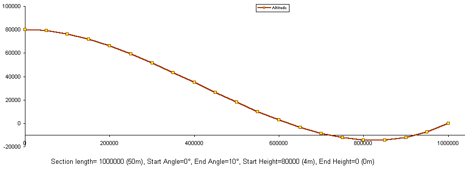
Look at these 3 example altitudes. Importantly, look at the numbers beneath each, so you can relate the numbers to the sort of curves you can create.
How were these curves calculated? If you don't want to do all the calculations yourself, File:Angledelta.zip is an Excel (97- if you want an earlier version I can convert it for you) spreadsheet that will let you type in the numbers (heights, angles, lengths) and have the delta values calculated for you.
The angles between trk sections are normally the same, i.e. angles at the end of section N are the same as the angles at the start of section N+1. This way, assuming that you aren't doing extreme elevation changes over short longitudinal distances, the track will be smooth. Having said that, you can use different angles at each section to create evil bumps to unsettle the car.
Limitations
Each altitude can only be quite simple in terms of the line the curve takes. E.g., to create a corner like Eau Rouge you require several pieces- down, flat, up, up, flat, etc. You cannot create everything in one piece!
Typically, for a hill, you will have one or two sections going up, one at the top, then one or two going down. There is a maximum of 16 traces per track. This has implications on the sort of elevations that you can create in a track. You may want to create kerbs or banking at all sorts of lateral positions around the track, but this is not possible because of the few traces available. So - plan where you want the traces before you start the altitudes, or you'll regret it later.
Altitudes are nice curves longitudinally, but laterally they are linearly interpolated. In other words, when you create cambered pieces of track, make sure that the angle of each piece (between traces) is the same, or the cars will be very difficult to drive.
Last updated: 18-August-2000
Transferred to the wiki: 30.04.2009


