GPL Track Creating - Trackside Objects
Authored by the GPLEA
Adding to your track
There are 6 ways you can add objects to your track, all of which use the .TSO file. he first three are ways of placing the object within the driving limits of the track. The second three are the same, but involve placing the objects on the infield or outfield of the track. They are:
(1) TSO entry type 1 - absolute x,y,z coordinates, absolute x,y,z rotations. This is the least used method, because it requires the most math. Look at the trk23dow.tso page for more information.
(2) TSO entry type 2 - longitude,latitude,z coordinates, absolute x,y,z rotations. This has been replaced by TSO entry type 3, the only difference is the absolute rotations, which I'm sure you can work out if you require this option.
(3) TSO entry type 3 - longitude,latitude,z coordinates, relative x,y,z rotations. This is the most used method of placing objects on your track. Here is an example TSO entry:
[ 11]: 3, 1839.4089, 0.0, -0.1016, 180.0, 0.0, 0.0, 1.0, mbridge comment
Hopefully you already understand what the numbers are, from the trk23dow.tso page. Here's a quick refresh anyway:
[ 11]: a human-only number to identify this object
3: TSO entry type 3
1839.4089 longitude - distance from start/finish line - in metres, of the 0,0,0 point of the object
0.0 latitude - distance from the centre line - in metres, of the 0,0,0 point of the object
-0.1016 z adjustment - distance from the track surface - in metres, of the 0,0,0 point of the object
180.0 xy rotation - rotation of the object in the top-down view
0.0 yz rotation - rarely used
0.0 xz rotation - rarely used
1.0 scale of the object - 99% of the time this is 1.0
mbridge object name
comment any old comment, for human purposes only
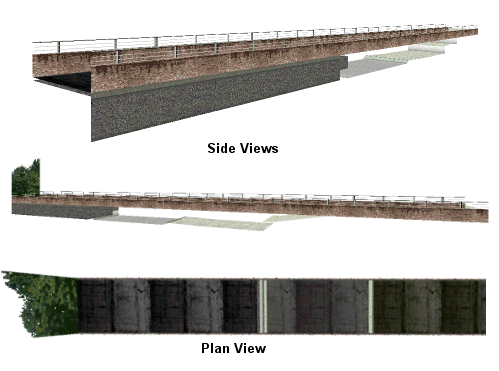
In this example, we have a bridge object being positioned so that it will fit entirely within one section (this is very important - see Avoiding Clipping for more details).
Figure 1. Here you can see how the bridge (the brown+railing parts only) fits in with the rest of the track. In Plan View, the bridge completely covers the track- if you were to see the next and previous track sections you would not see the bridge at all- this is A Good Thing.
Z Coordinate
You may be wondering why the Z coordinate of the object is negative? This is because the object was designed to fit the track section, but it was designed for a flat piece of track. When the track was changed, the piece of track the bridge was designed for was made into a slope, so to make the bridge fit again, a slight adjustment was required
Infield/Outfield Object Placement
Sometimes you don't want an object within the driving limits of the track- in fact, a great number of object in the original Papyrus tracks are outside the driving limits. One very good reason for placing objects on the infield/outfield is that the problem of clipping is greatly reduced, because there is no track to clip with. You can also have objects that are 'next to' several track sections, which you cannot have with the in-driving-area objects.
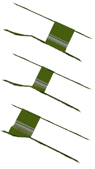
Figure 2. Here is an example from Rouen, where three consecutive track sections all reference the same two outfield objects - a row of trees on the left, and the right, of the track. In other words, the tree objects are 'next to' all three track sections.
To use the infield/outfield object placement, you must reference each track section that the object is next to, in the .TSO file. The trk23dow.tso page details this in more detail. You will, however, have to update these references if you change the track layout, so it is worth getting the track layout finished before you start with the infield/outfield objects.
Avoiding Clipping
Clipping is a very annoying problem. It is caused when polygons are drawn in the wrong order- overlapping each other incorrectly. Here is a cause-remedy table that should help:
Cause/Problem
An object appears through another one - e.g. a row of houses all in one track section.
Remedy
Change the order of the objects in the .TSO file so that the furthest away object (when driving normally) is listed first, the nearest object last.
Cause/Problem
Object appears to float/sink.
Remedy
Check that the object is matched with ground-level. If it is, check that it lies completely within the track section (see bridge example). If it still clips with the track, make sure it lies completely within the left-right bounds. These bounds are defined by armco, walls, and the left/right edges of the driving area.
Cause/Problem
Several objects lie in a group near each other, clipping with each other from various angles.
Remedy
If changing the .TSO order of the objects does not help, and you cannot move some objects to another track section, you will have to rebuild the objects as one 3DO. The buildings near the bridge at Silverstone are a good example of one object-many buildings.
Creating new objects
Creating new objects is a very time-consuming task. If you want to, here is a tutorial. You are also advised to read all the pages at GPL File Formats. An understanding of vertices, planes, normals, texture mapping and Binary Space Partitioning is very useful as well.
Updated 6-Jan-2001
Transferred to the wiki: 23.04.2009

